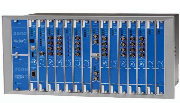
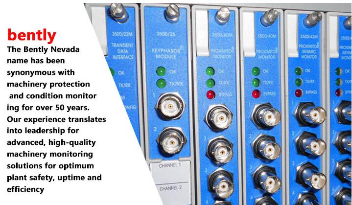
Description The 3500 Transient Data Interface (TDI) is the interface between the 3500 monitoring system and GE’s System 1® machinery management software. The TDI combines the capability of a 3500/20 Rack Interface Module with the data collection capability of a communication processor such as TDXnet. The TDI operates in the RIM slot of a 3500 rack in conjunction with the M series monitors (3500/40M, 3500/42M, etc.) to continuously collect steady state and transient waveform data and pass this data through an Ethernet link to the host software. Static data capture is standard with the TDI, however using an optional Channel Enabling Disk will allow the TDI to capture dynamic or transient data as well. The TDI features improvements in several areas over previous communication processors and incorporates the Communication Processor function within the 3500 rack. Although the TDI provides certain functions common to the entire rack it is not part of the critical monitoring path and has no effect on the proper, normal operation of the overall monitor system. Every 3500 rack requires one TDI or RIM, which always occupies Slot 1 (next to the power supplies). For Triple Modular Redundant (TMR) applications, the 3500 System requires a TMR version of the TDI. In addition to all the standard TDI functions, the TMR TDI also performs “monitor channel comparison”. The 3500 TMR configuration executes monitor voting using the setup specified in the monitor options. Using this method, the TMR TDI continually compares the outputs from three (3) redundant monitors. If the TDI detects that the information from one of those monitors is no longer equivalent (within a configured percent) to that of the other two monitors, it will flag the monitor as being in error and place an event in the System Event List.
A: Transient Data Interface Type 0 1 Standard (Use for standard monitoring applications) 0 2 TMR (Use only for applications that require a Triple Modular Redundant Configuration).
B: I/O Module Type 0 1 10Base-T/100Base-TX Ethernet I/O module 0 2 100Base-FX (Fiber Optic) Ethernet I/O module
Outputs Front Panel LEDs OK LED:
Indicates when the 3500/22M is operating properly
TX/RX LED:
Indicates when the 3500/22M is communicating with the other modules in the rack.
TM LED:
Indicates when the 3500 rack is in Trip Multiply mode.
CONFIG OK LED:
Indicates that the 3500 rack has a valid configuration.
I/O Module OK Relay:
Relay to indicate when the 3500 rack is operating normally or when a fault has been detected within the rack. User can select either an “OPEN” or “CLOSED” contact to annunciate a NOT OK condition. This relay always operates as “Normally Energized”.
OK Relay:
Rated to 5A @ 24 Vdc/120 Vac, 120 Watts/600 VA Switched Power.
Normally closed contacts:
Arc suppressors are provided.
Controls